This project is a culmination of 11 weeks spent learning how to navigate a lathe, 3D printers, mills, sand casting, and bead blasting. This manufacturing class helped me to contextualize both design engineering and designing for manufacturing. Students were given the freedom to choose anything they wanted to build, and I decided to make a chess board. Before I talk about the steps in my project, I would like to give a brief overview of the five main manufacturing processes I used, as not everyone is familiar with them.
Sand Casting:
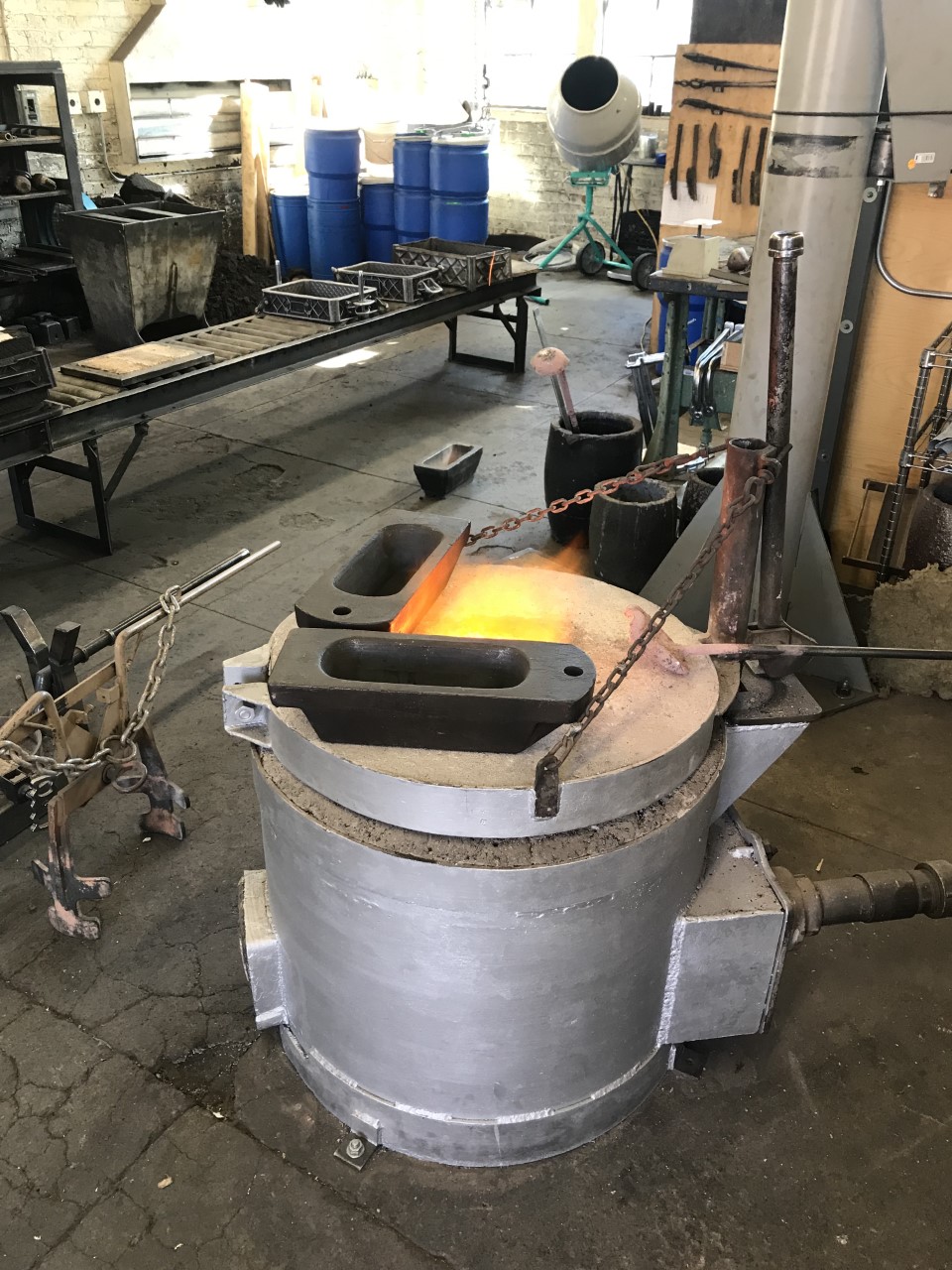
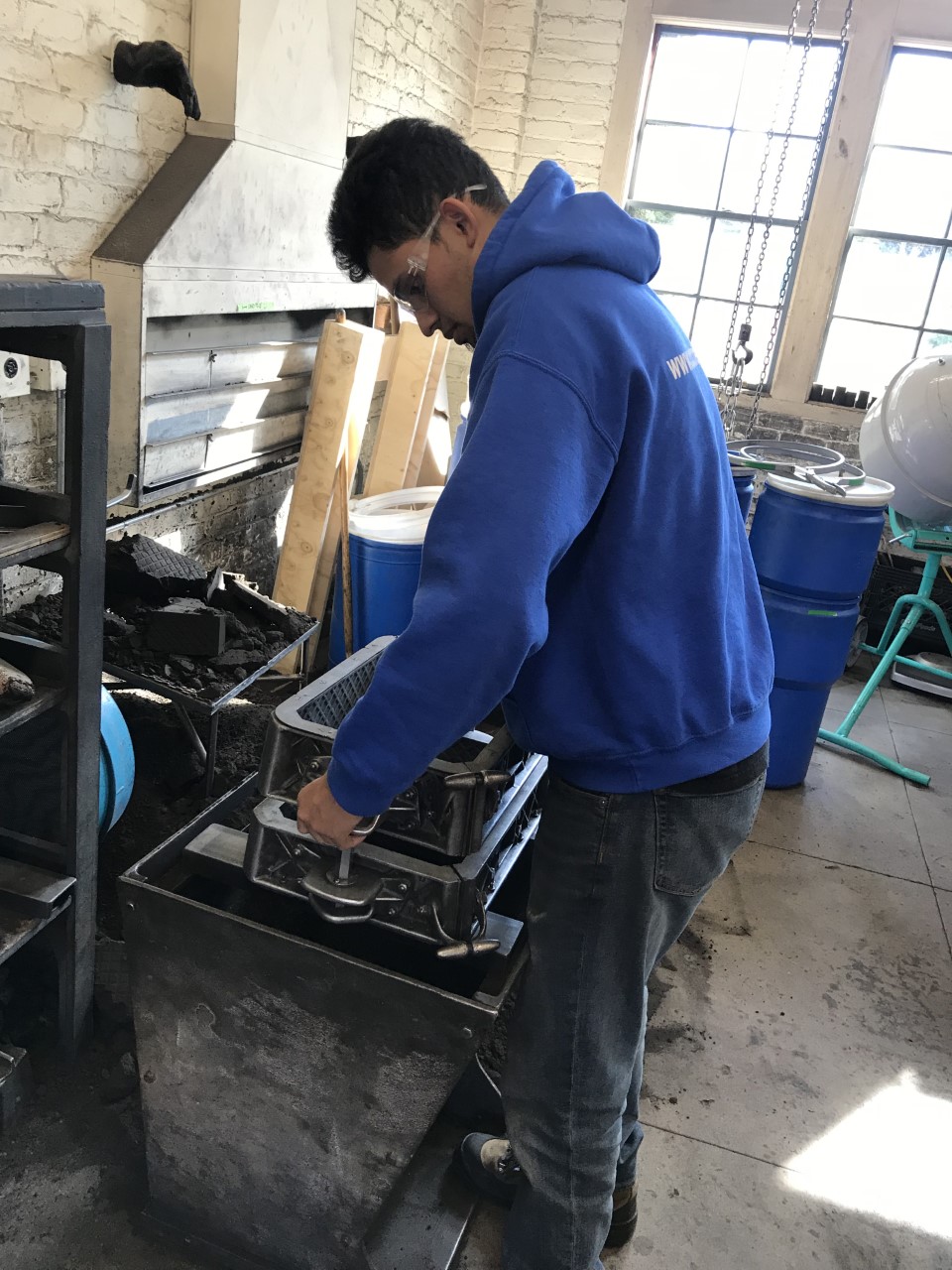
A metal casting process that uses sand as a mold material. A pattern is placed in a large metal container called a snap flask, and then filled with sand. The pattern is then taken out of the snap flask, and the remaining packed sand holds the shape of the pattern. Molten metal is then poured into the sand mold. After the metal cools and becomes a solid, the sand is removed and a metal piece remains.
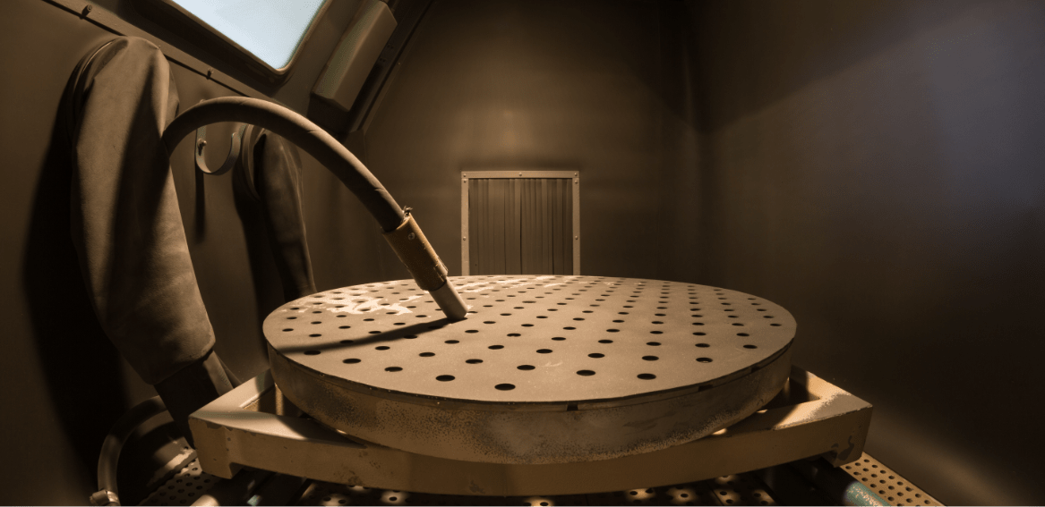
Bead Blasting:
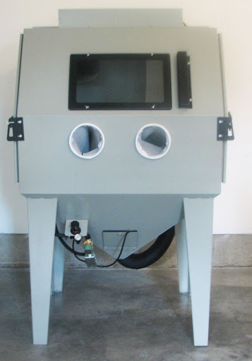
A process where glass particles are shot at high speeds to scratch the surfaces of materials, creating different textures.
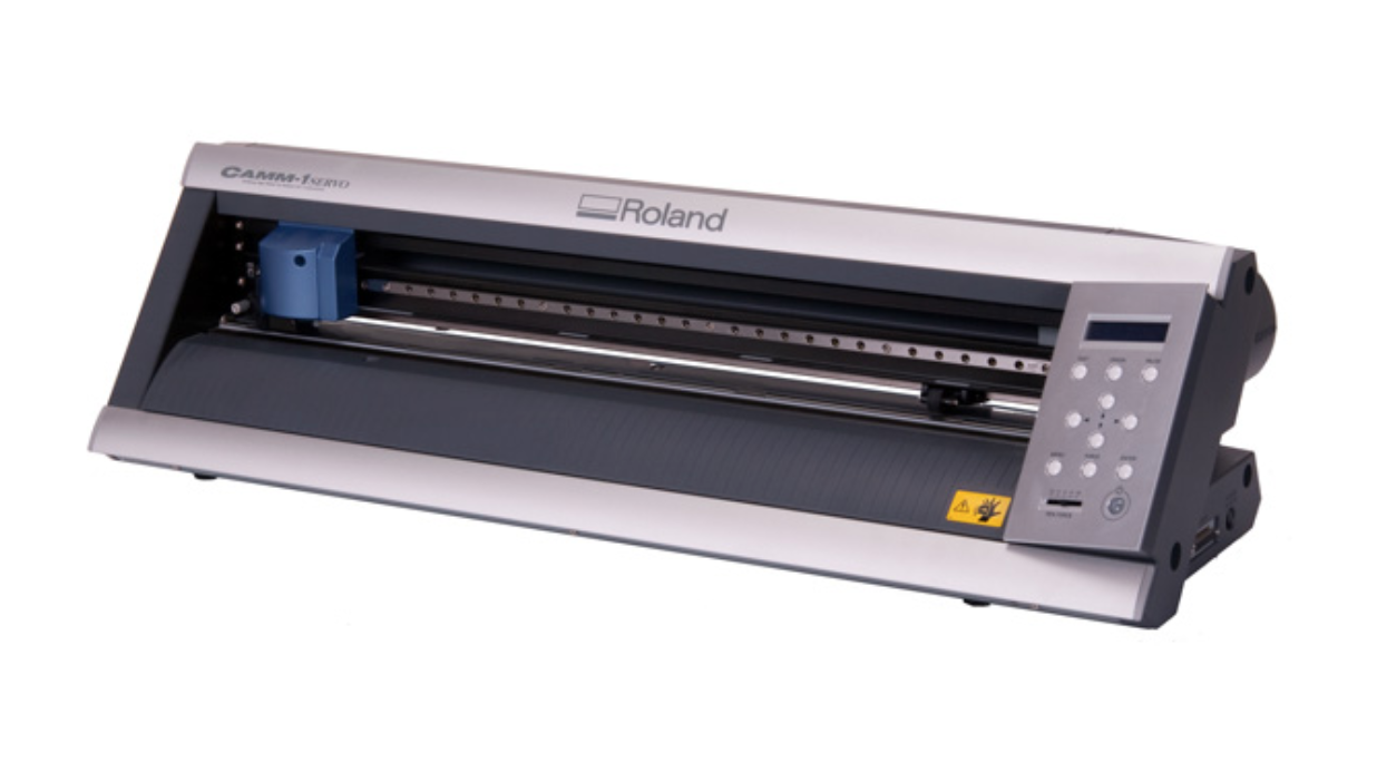
Vinyl Cutting:
A process that uses vinyl rolls to cut stickers out of programmed geometries.
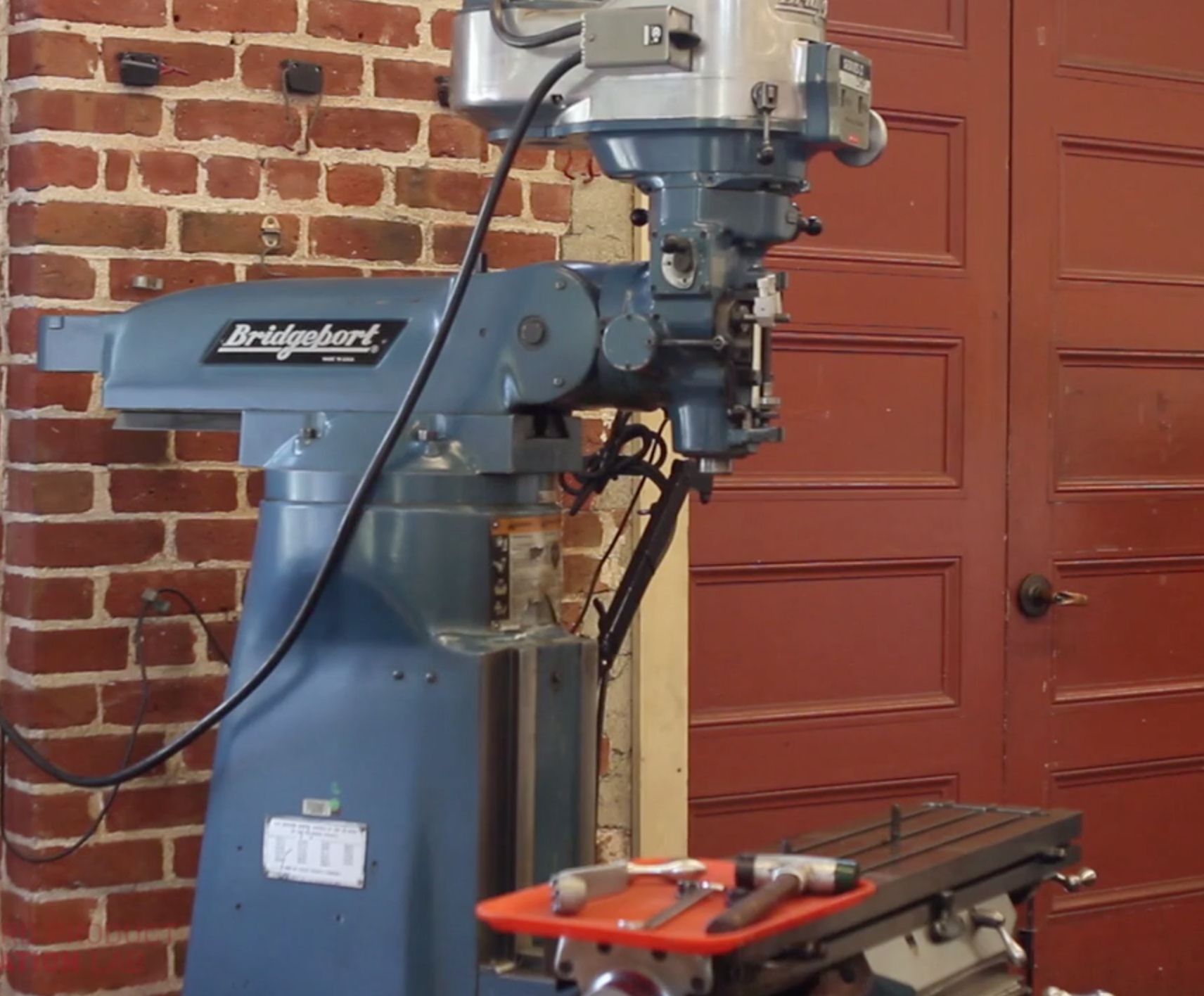
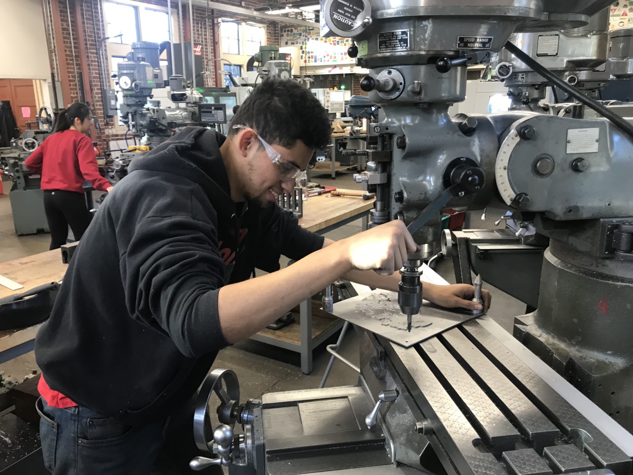
Manual Mill:
A machining process that uses a rotating cutter on a work piece to remove material at an angle. The cutter moves in the z direction, and the workplace can move in the x and y.
Manual Lathe:
A machining tool that is used for symmetrical cross sections. Can be used to drill and tap holes. Work place can move in the x and y direction, and the cutter can be adjusted to cut at different angles.
Project Motivation:
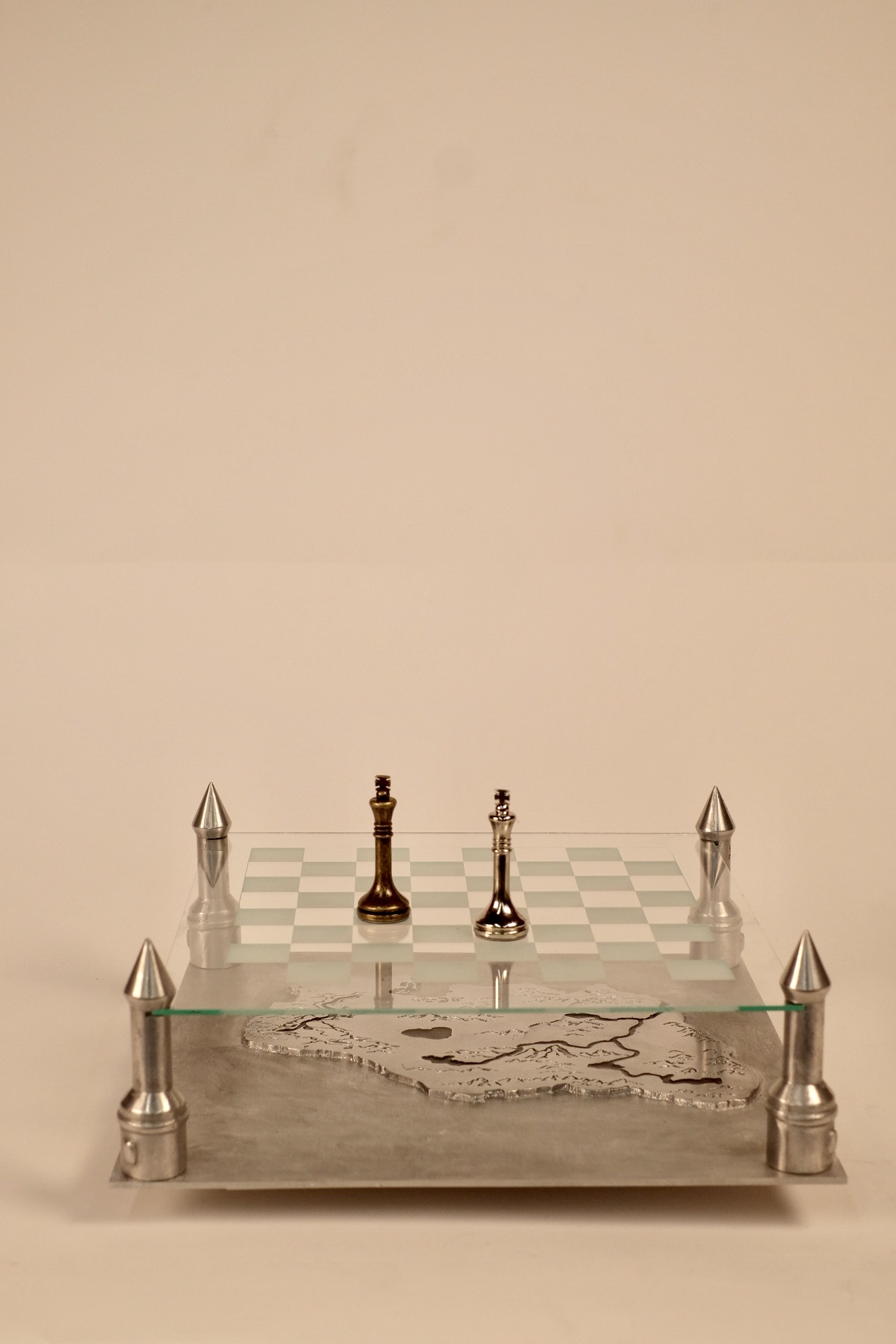
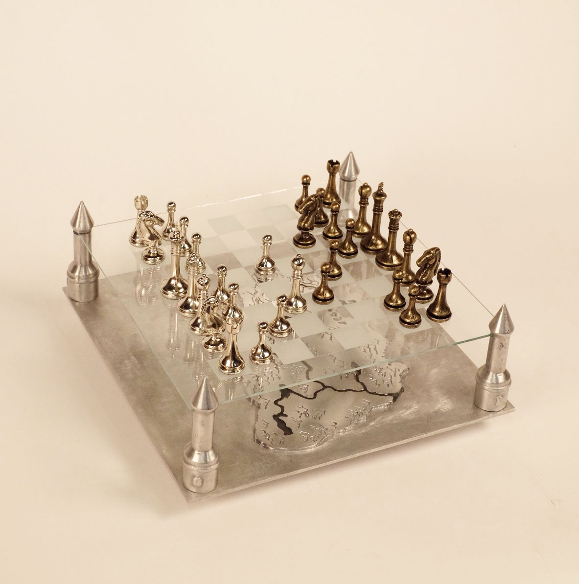
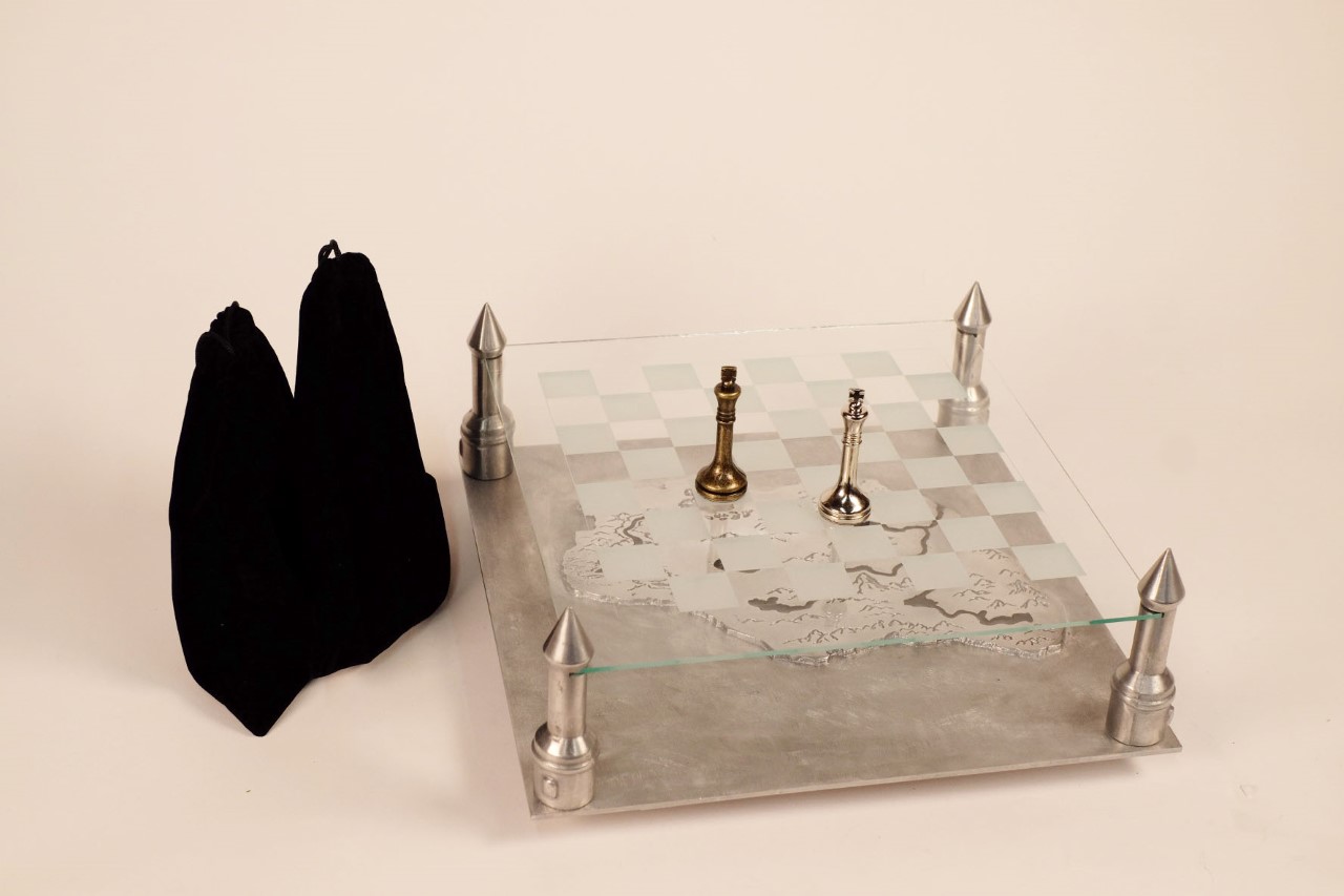
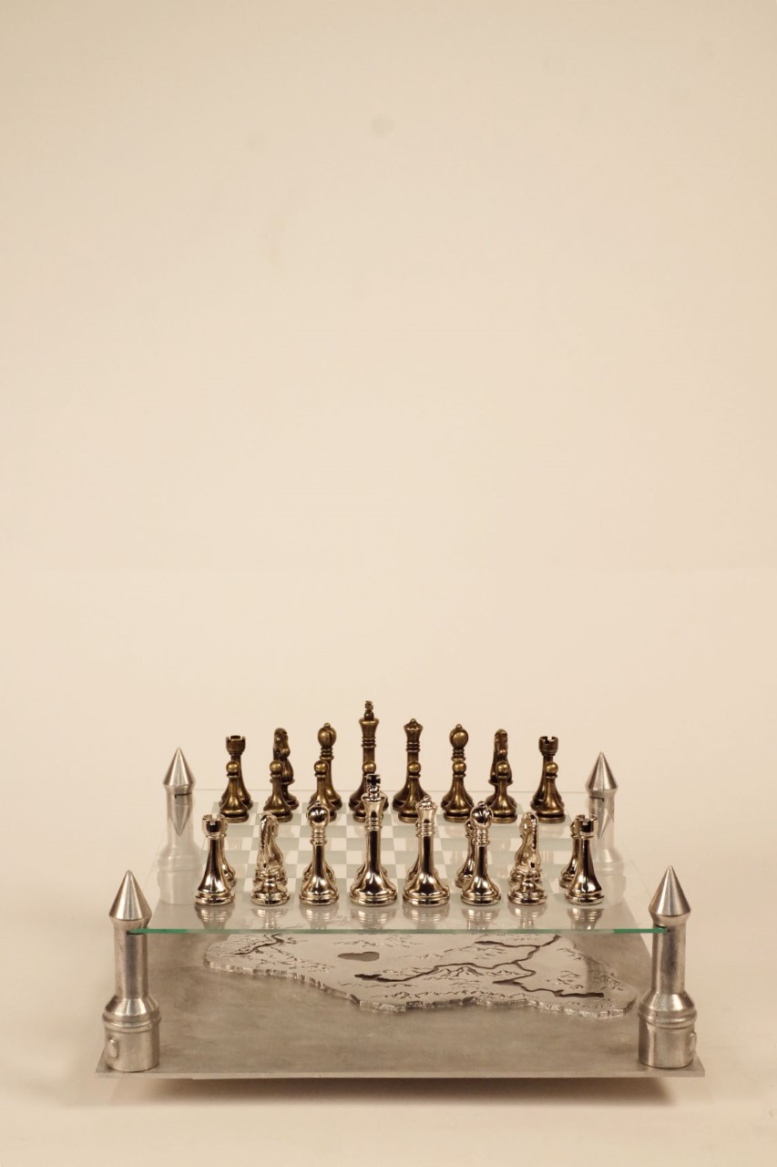
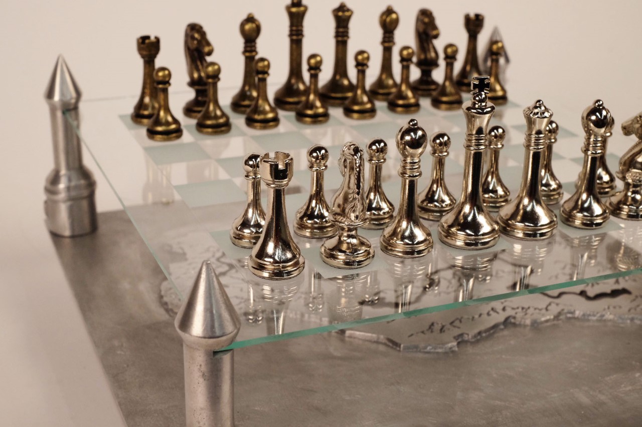
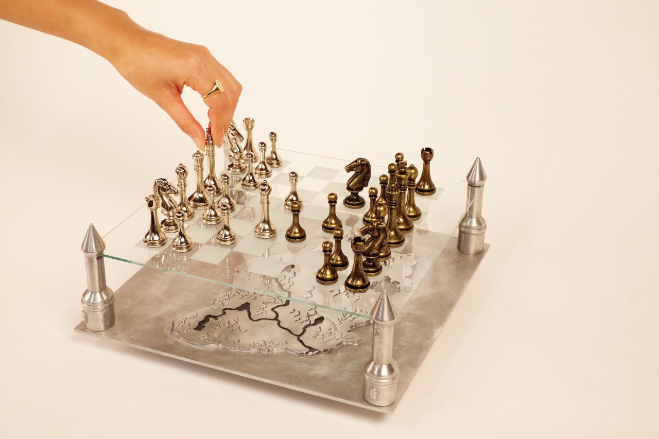
I grew up surrounded by family, and I would often challenge my uncles and cousins to duels in Chess. This chess board I built is a small homage to my childhood, and the purpose of making it would be to display it in my house as a beautiful centerpiece. This chess set is also a symbol for all the knowledge and skills I have gained during my time in school. Whenever I play on this board, I want it to serve as a reminder of my family and my experience at Stanford. I know I’ll always remember the burning smell of metal in the foundry, the smell of wood chips in the shop, and the hours spent pounding at sand.
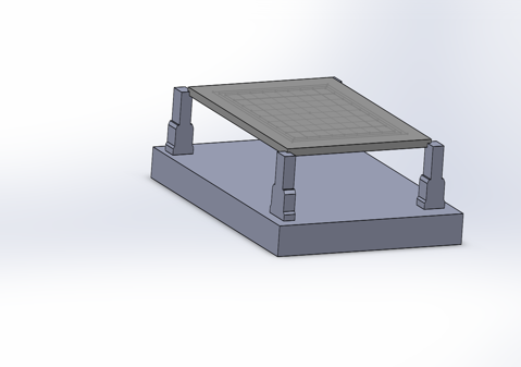
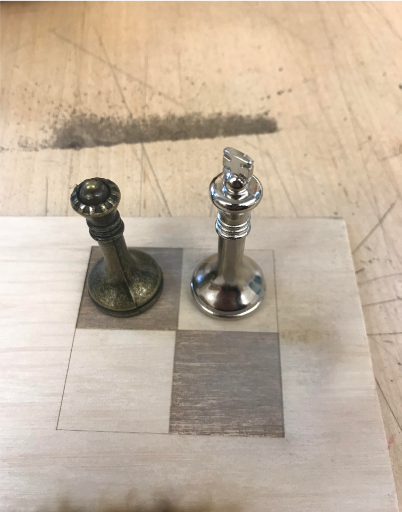
Initially, I struggled trying to find a way to incorporate a personal spin on a chess board. However I decided that I would make stands that were in the shape of castles. My first prototype was mainly a display that it could support a small amount of weight. Based on my research, I found that the chess pieces I wanted to use for my board weighed about 1-1.5 pounds. I found that the prototype could indeed support this weight, even with a simple thin piece of acrylic.
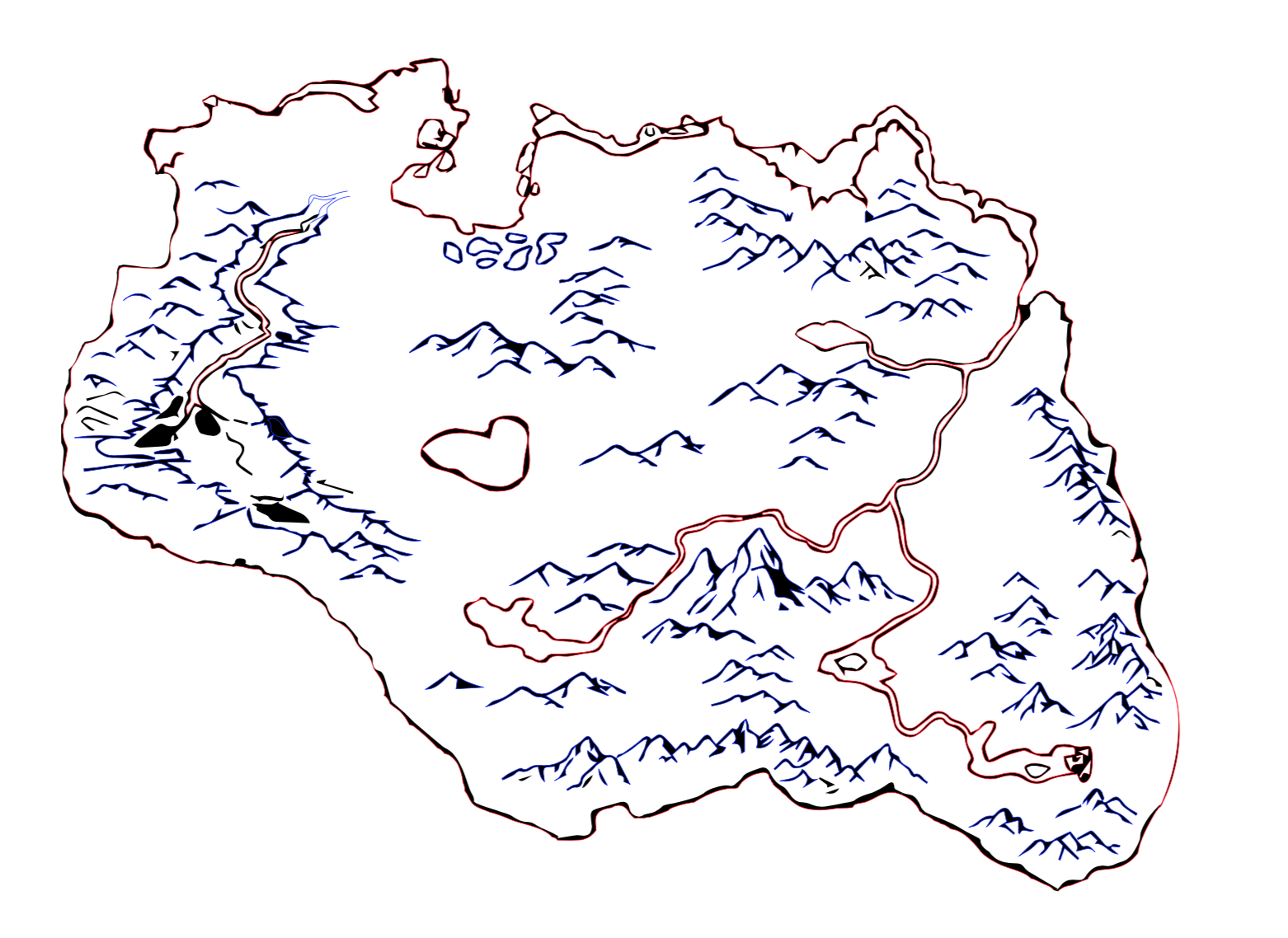
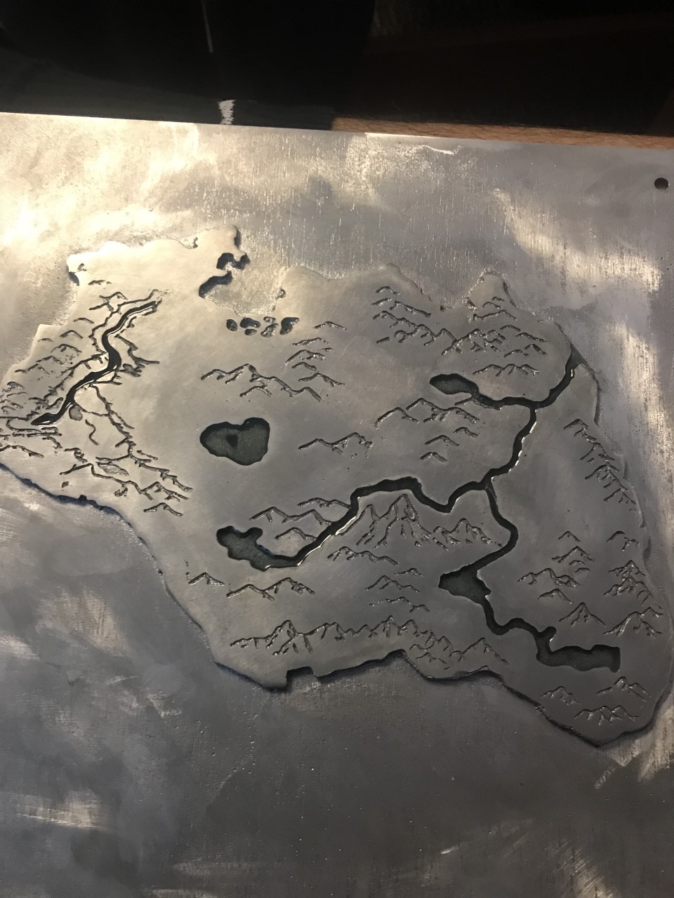
To add another personal element to my chessboard, I decided to recreate the Skyrim map from the popular video game and have it serve as a visual tether to the base of the chessboard. I thought that having this mythical theme would further add to the aesthetic I wanted to achieve with my board. After deciding on all the components of my board and testing for functionality, I decided to separate my project into three different sub projects. First, I would be sand casting my four castle stands using a pattern board. Second, I would be sand casting the map base as a loose pattern. Finally, I would make the chessboard pattern out of glass.
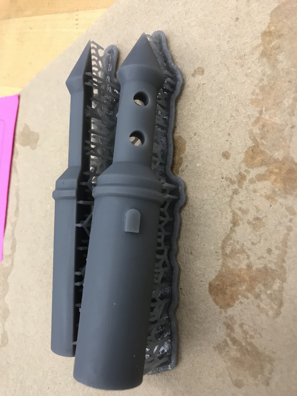
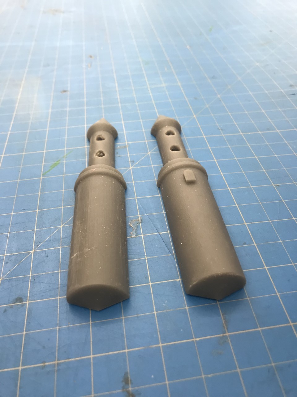
Castle Stands:
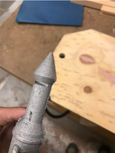
1. Use solidWorks to make a CAD model
2. 3D print the model in two different halves
3. Place the two halves on the opposite sides of a pattern board and align them
4. Make a gate and runner for the pattern board
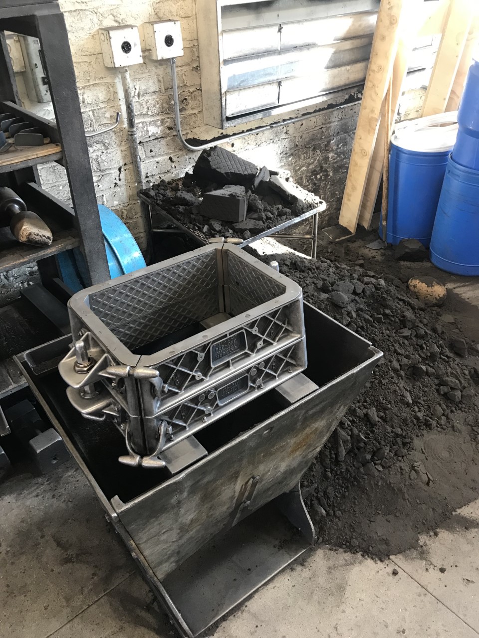
5. Place the pattern board in a snap flask to ram up, and repeat until four good parts came out.
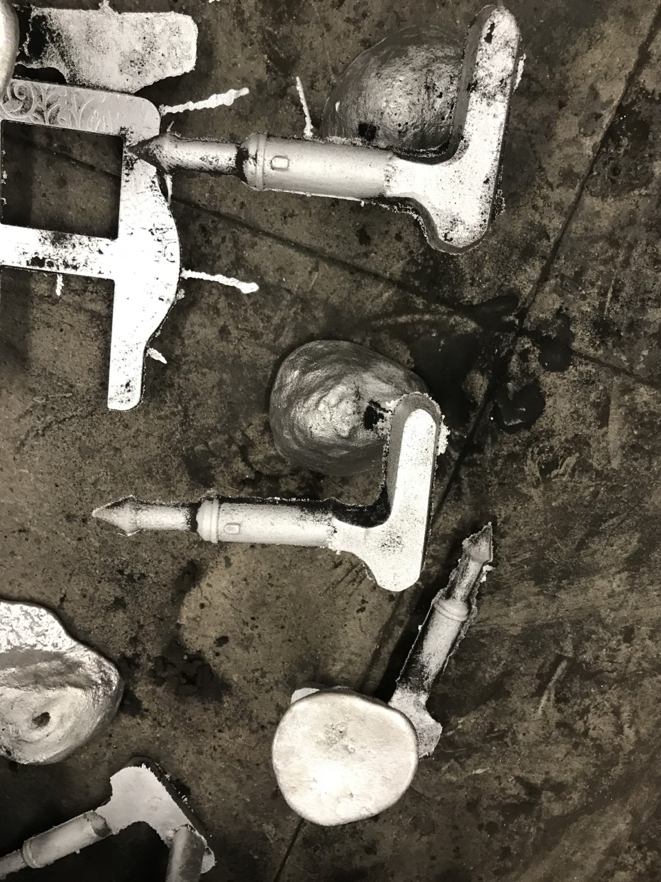
6. Hacksaw gates and runners off of parts
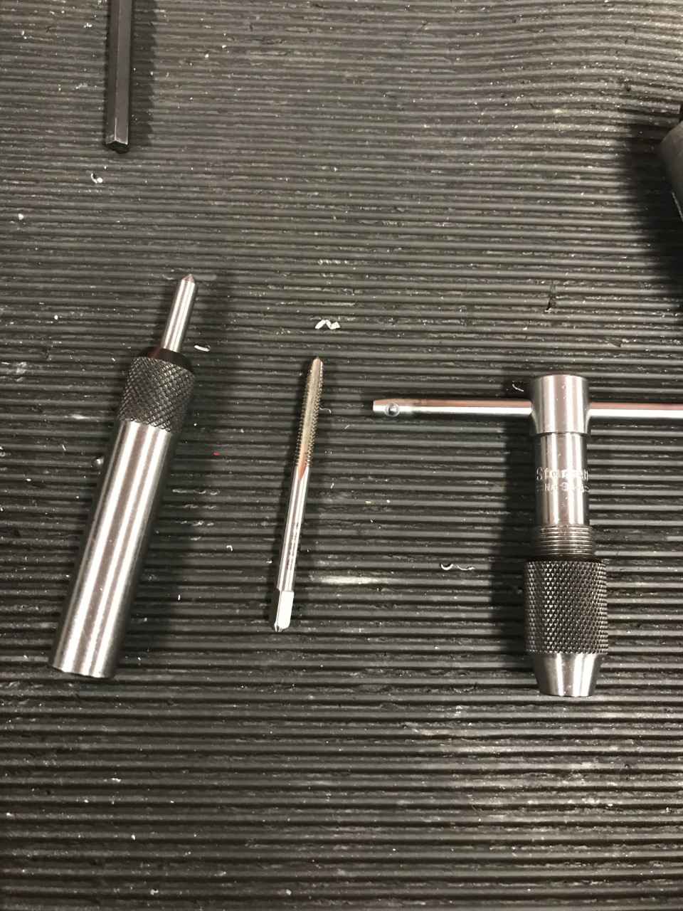
7. Tap the bottom faces of the castles using the lathe
8. Cut slits into the sides of the castles for glass board to rest in
9. Polish and buff castles for shine
.PNG)

My first CAD model design proved to be too complex to sand cast, as a lot of the different geometries had undercuts and could not be drafted. Thus, my second design was much simpler and allowed me to focus more on printing.
.jpg)
After the 3D printed parts were ready, I made sure that they were aligned on the pattern board by placing two sticks through the holes in the parts that would hold the pieces on either side of the pattern board.
.jpg)
.jpg)
After my first castle stand was cast out of the aluminum, I started practicing how to cut them with the slit end mill and how to tap and drill holes into the bottom sides so that they could be attached to the aluminum base.
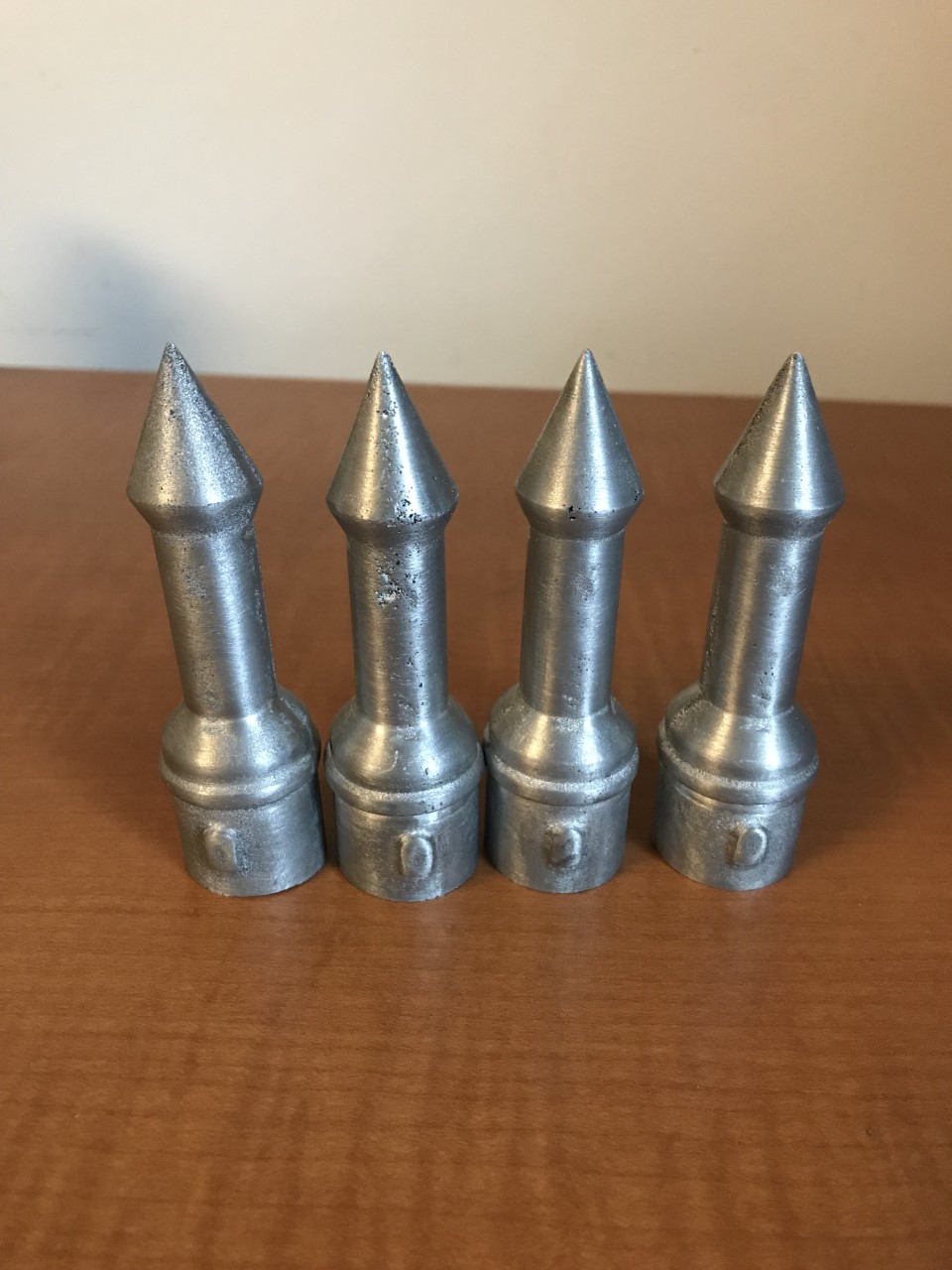
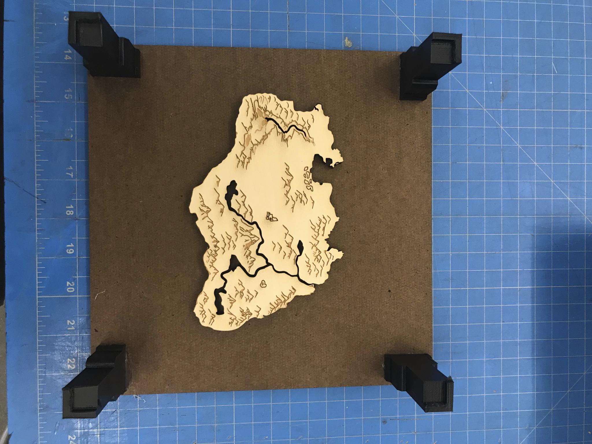
After my four castles were completed, it was time to move on to the aluminum Map Base.
Map Base:
1. Laser cut positive of map out of acrylic
2. Glue positive on 12x12 birch plywood
3. Use negative of map and glue on the bottom of the first piece pf birch plywood (for constant wall thickness)
4. Make a gate and runner
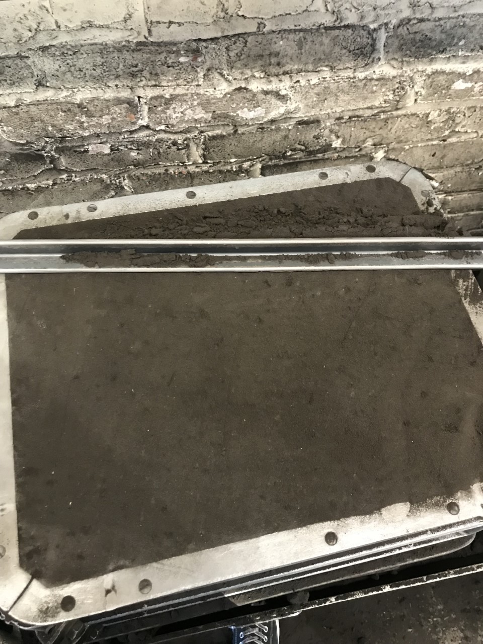
5. Place the loose pattern in snap flask and ram up
6. Cut off gate and runner
7. Drill four counter bore holes into the corners
8. Sand and polish
9. Fill river crevices with blue epoxy resin
.jpg)
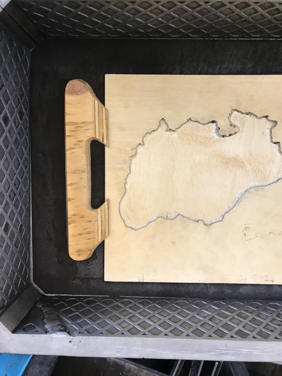
.jpg)
After I successfully created my loose pattern mold, I moved on to make the gate and ram up to see how it pulled from the sand.
.jpg)
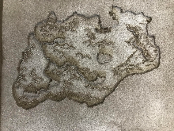
.jpg)
As seen above, there was a dramatic difference in the amount of detail achieved in both the sand pattern and the sand cast aluminum part itself from the first to third iteration. There was a big learning curve and I had to experiment with different ways of ramming up, adding filets, and using a dremel to make draft angles more pronounced in the mold.
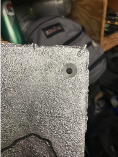
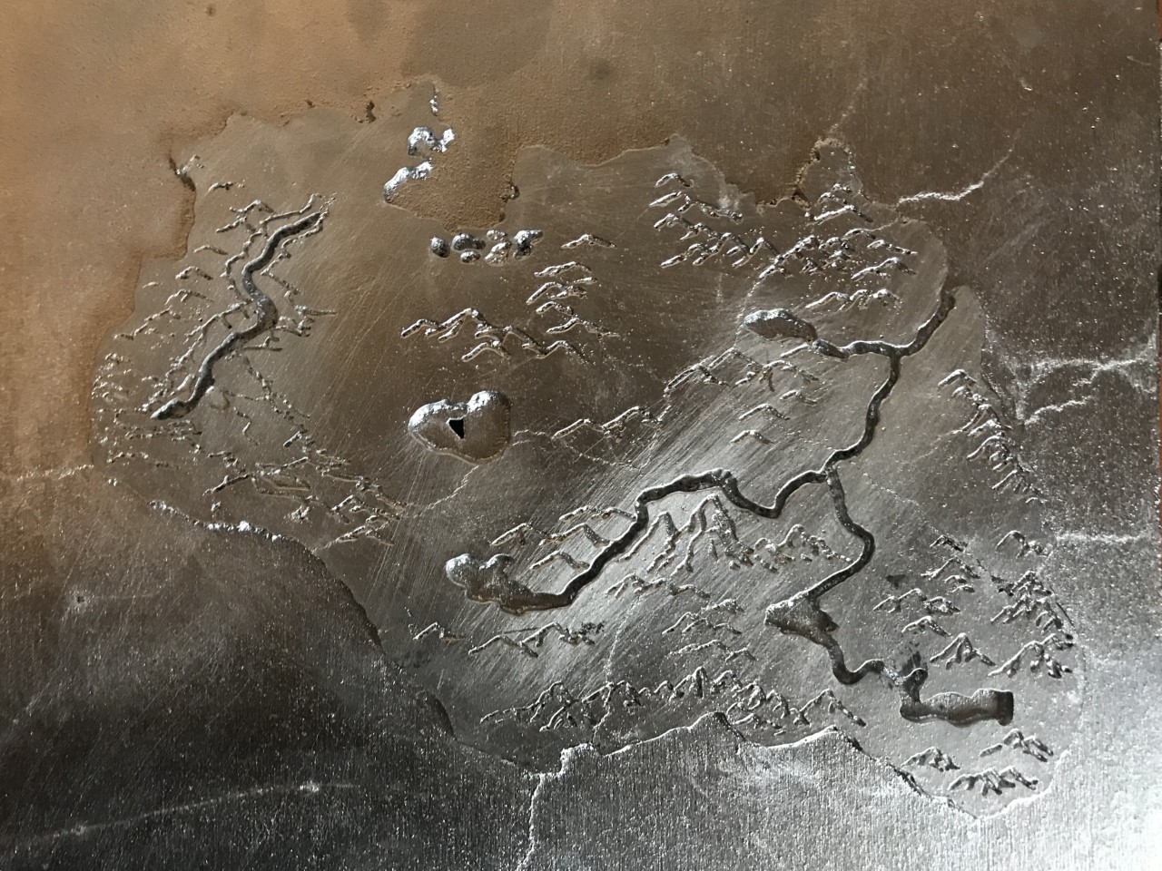
After the base was sand cast, I used a face mill to clean up the sides of the base, then I drilled counter bores into the four corners.
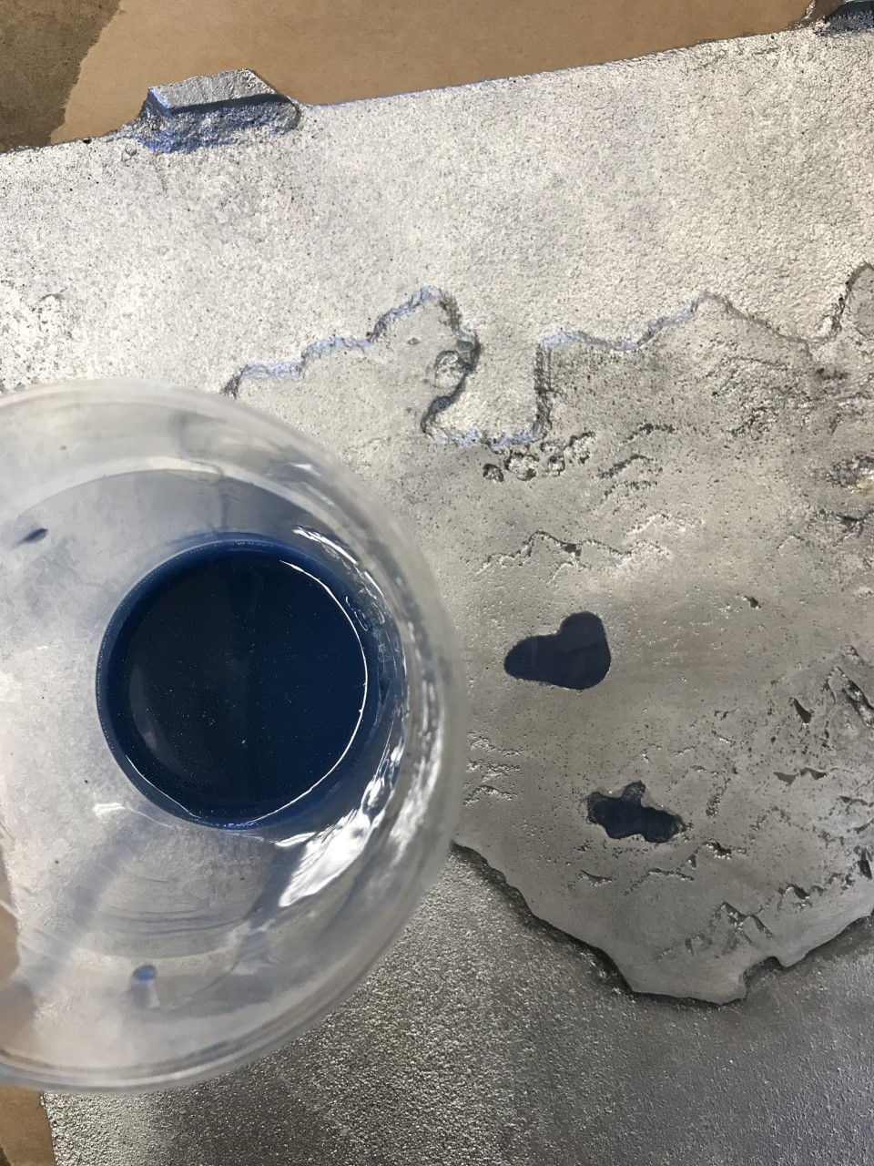
The final step to completing the base involved using an epoxy resin, a viscous material that hardens after setting, with blue dye to achieve a more realistic river effect in the map. With this final step completed, it was time to work on the glass board.
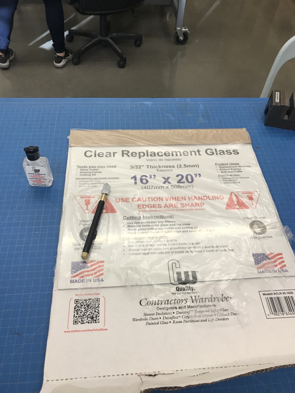
Glass Board:
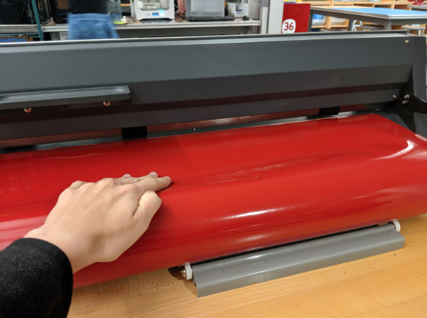
1. Use vinyl cutter to print out a sticker pattern of the chess squares
2. Use glass cutter to cut stock glass to size
3. Place sticker on glass and bead blast for textured squares
.jpg)
The first steps to creating the glass board involved testing different dimensions for the squares to make sure the purchased chess pieces did not look too big or too small inside of them. I ended up deciding that the max square width would roughly be about 75% more than the diameter of the king's base. After the dimensions were decided, I had a practice run on a small piece of glass.
After the practice bead blast run, I finalized the final dimensions of the chess pattern and vinyl cut it out of a black sticker.
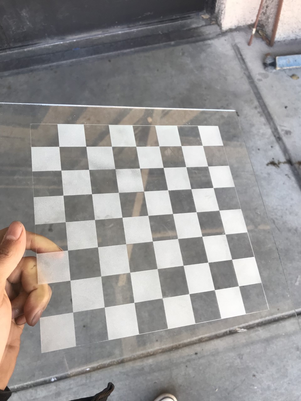
Finally, the glass stock was cut to size. I then placed the vinyl cut sticker on it and bead blasted the covered surface. With the final piece finished, it was time to start the final assembly.
Initial Assemblies:
.jpg)
.jpg)
.jpg)
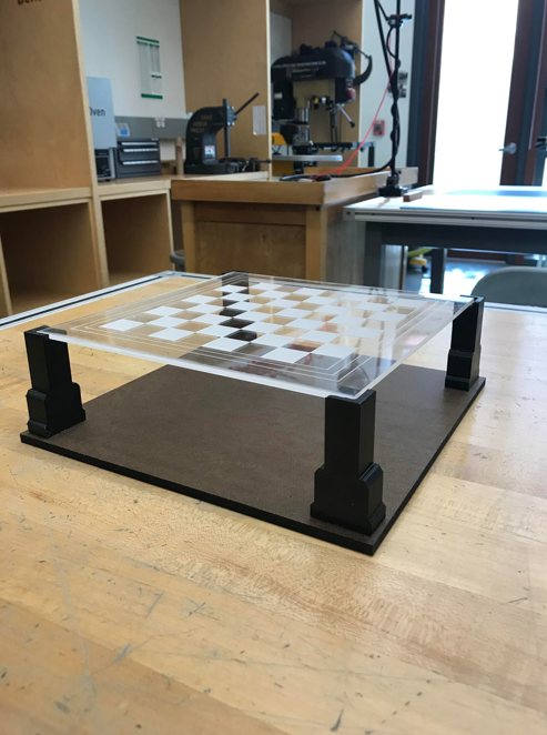
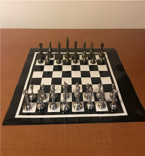
Final Product Pictures:
My time spent in this class was truly an adventure that taught me many things. I came into the course knowing absolutely nothing about manufacturing processes or how I could make my designs into physical things. I was very intimidated by the product realization lab, but as the class progressed I became more confident and was able to create a project that I will be proud of for the rest of my life.