Solar Panel Heat Reclamation
A senior capstone project focused on increasing solar energy capture
This capstone project is the culmination of 22 weeks worth of design, research, manufacturing, and experimentation. Due to a limited amount of space, this will only be a brief overview of the project. There is a full technical report that documents every part of this project that can be made available through contacting me.
As of 2019, the highest rated solar PV panel is only about 22.8% efficient, with a majority of panels only being 15% to 17% efficient. Of this 70-80% of unused solar energy, about 45% gets converted to thermal energy radiated off of panels and trapped underneath panels, and the rest is lost to photons passing through the solar cells. Given current residential solar PV panel installation practices, this thermal energy ends up primarily stuck in the small gap between the panels and roof. This region of untapped thermal energy is what my team decided to target in this project.
For the purpose of our project, my team decided to primarily focus on capturing and transporting the trapped thermal heat. While our research does show potential uses for this heat, our time constraint has led us to believe that we should solely focus on the thermal capture portion of our project. We have collected enough data to prove our work has some significance, and hope to continue our research later on.
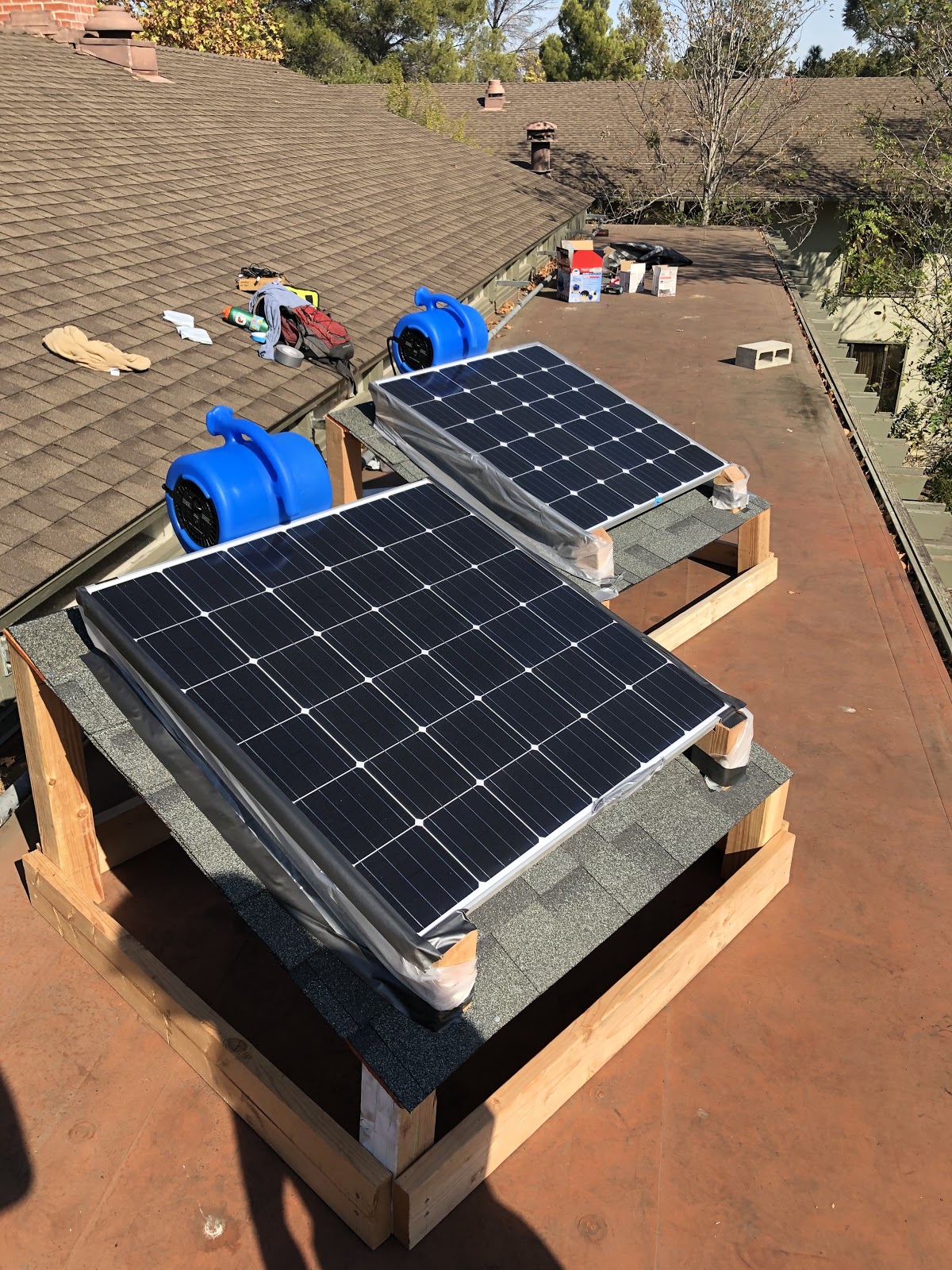
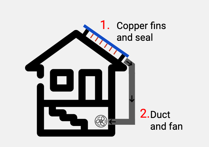
Our initial prototype proved a couple of things about our design: First, we showed that copper fins underneath the panels helped pull more heat off their base. Second, we were able to show that we could create a seal to allow air to flow from the blue fan at the top of the panels to the bottom of the panel.
Adding copper fins underneath the solar panels had a notable change in the amount of heat we were able to push out, with the Q average for our set up with fins being about 24 watts more than our set up with no fins. This directly translated to our fin setup having a Max COP of about 1.42. Moving forward, we decided to research how geometry and formation in pin fins affected heat sinks. We hoped that this information could provide a different approach to designing our new set of fins. We also decided to focus on creating a stronger seal, adding ductwork, and making our fans internal versus external.
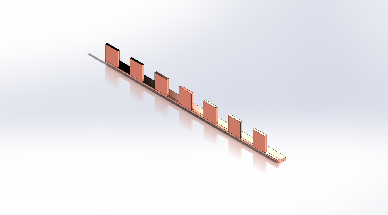
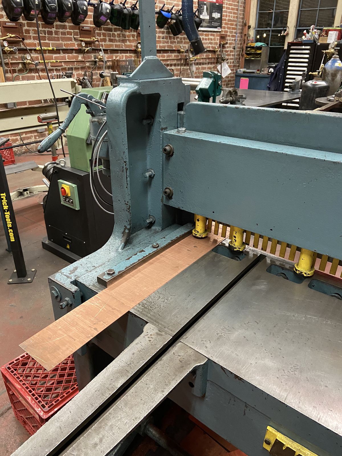
The first two properties we found to be of interest was that staggering fins in an array resulted in more turbulent flow with a higher heat transfer rate. It was also shown in a research paper that rectangular pins had the best thermal performance, the highest entropy generation rate, and the least amount of drag force when compared to other geometries. Taking all of these properties into account, we decided to manufacture a set of staggered rectangular fins for our panels. For the purpose of our tests, we decided to test two different directions for airflow. One would be perpendicular to the rectangular fins, and the other would be directly parallel to the faces of the rectangles.
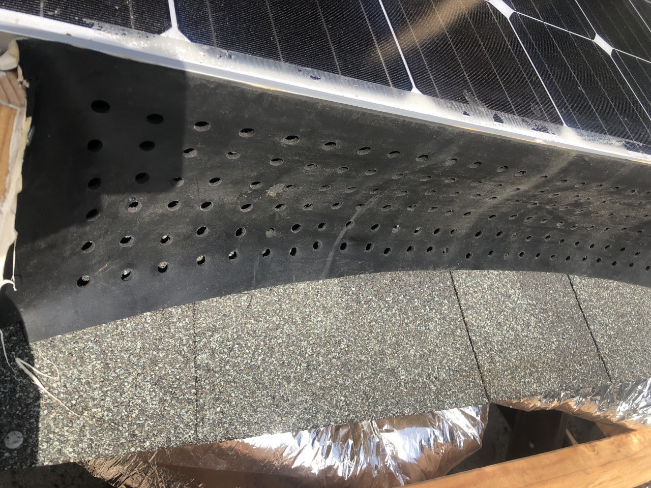
Next, we wanted to focus on creating a stronger seal. Since our new design would have air being sucked through the system, a tighter seal was even more important. We needed a material that was airtight, flexible, a good thermal insulator, and inexpensive. Moreover, we wanted to minimize our impact on the environment and make sure that the material was easy to recycle. After careful research, we found that butyl rubber was a good match for our requirements.
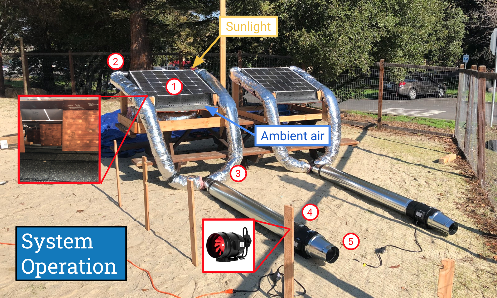
Finally, with aluminum tubing and flexible HVAC ducts, we were able to create our thermal transport network. As seen above, our full system uses a fan located at 4 to draw in hot air from underneath the panels and through the ductwork.
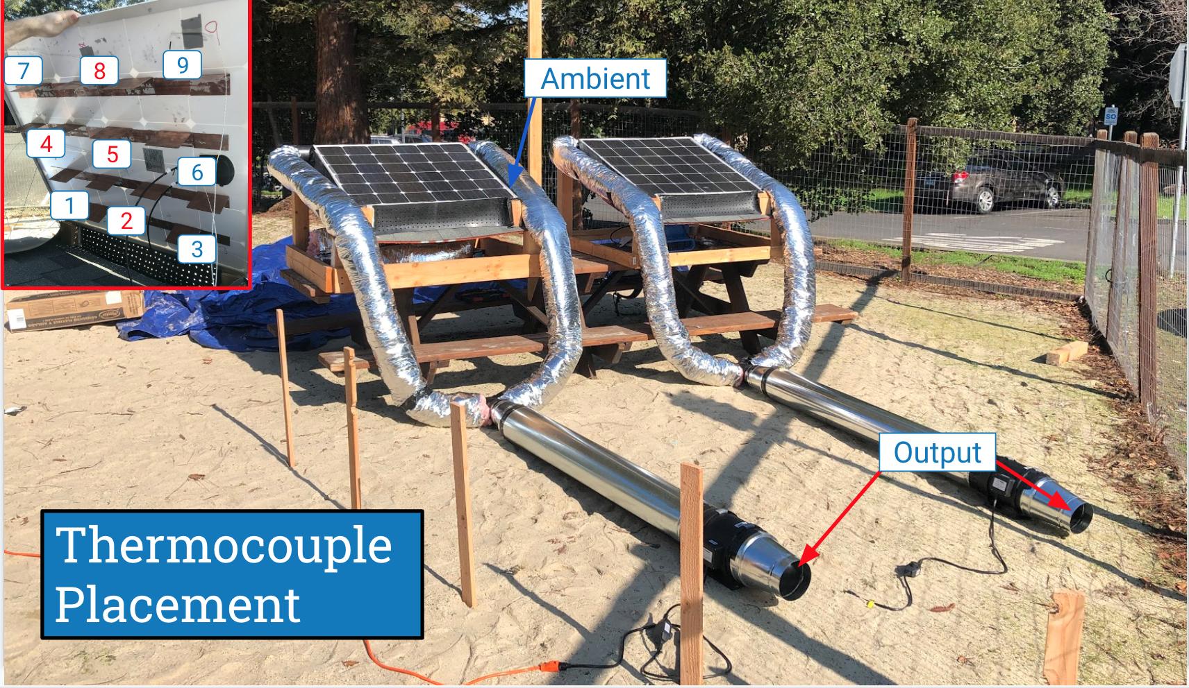
The next step in figuring out what was going on with our system was to start measuring temperature differentials from our ambient inlet, to our output. With this information, my team was able to measure the amount of power we were drawing from underneath the panels, as well as the COP of our system (Coefficient of Performance = energy in/energy out).
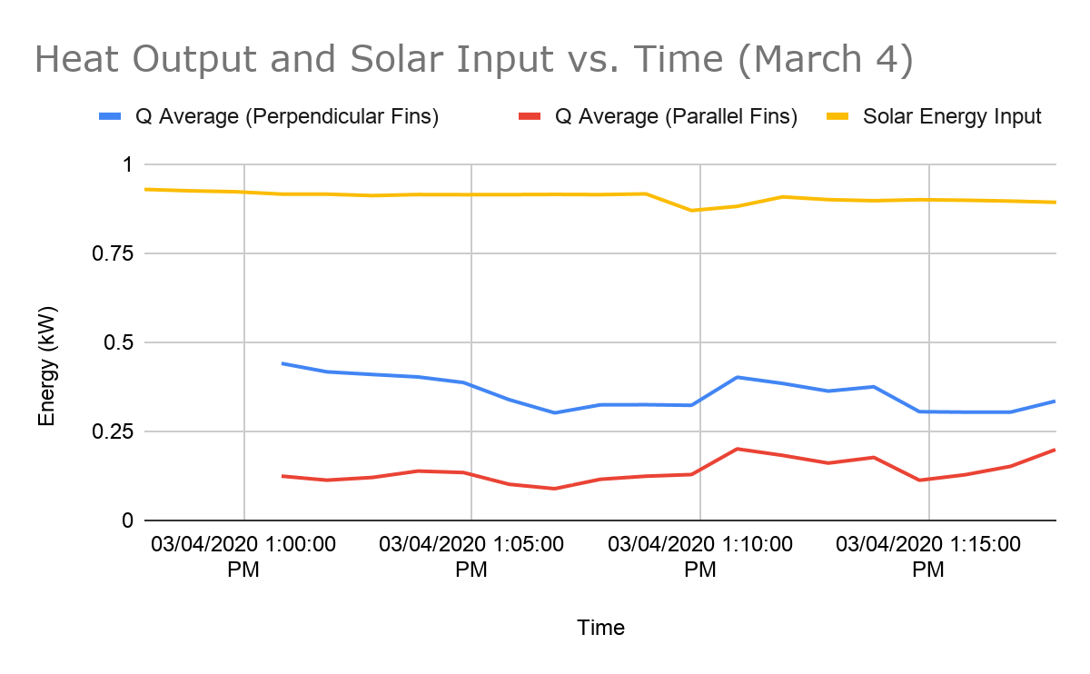

After we collected data for various days, we were able to refine our experimental design and mitigate a lot of the noisy data we were getting during the first rounds of data collection. The top two figures show data from our best day of testing. As seen in the average heat output and COP columns, the perpendicular fin orientation was more efficient than the parallel fins. We were able to consistently capture 366 watts worth of energy with a COP of 3.3, increasing solar energy capture from 15% to 40%. This is a very important finding, as clean energy is becoming a necessity in today's society. If we were able to work on this project for another six months, we would aim to figure out how our system could potentially integrate with a home’s heat pump or electrical thermal generator. This interface is another complex area that we have not explored fully, and could prove to be a challenge in its own right. Similarly, our team wants to integrate some type of thermal activated control system to the fan system. This would alleviate the problem of extracting unwanted heat during a hot day, and automatically turn off the system if the temperature differential between ambient and panel backside temperature is not large enough. Finally, we would have to consider the issues of scaling up. This includes getting a fix on a bill of materials and transformation/installation cost. With all of these numbers in place, we would finally be able to give an estimated ROI to our potential customers.